Edition
All the edition tools are regrouped in the menu Edition, which contains the following elements:
Draw D
Modify feature M
Draw Bezier P
Modify Bezier A
Bezier Settings
Remove last vertex Ctrl+Z
Edit vertex Ctrl+V
Insert Vertex I
Delete Vertex C
Move shared node Ctrl+T
Delete feature Delete
Cut line Ctrl+X
Merge lines Ctrl+F
Create interection Ctrl+I
Flip line Ctrl+Alt+F
Smooth line Ctrl+Alt+S
Snapping
Edition tools
To edit objects with the different tools in ToolMap you will have to enter the edition mode.
Select the layer to edit in the table of contents
Activate the Edit Layer option in the pull-down menu
This operation activate the edition menu
Important
Only the construction layers (displayed in bold in the table of content) can be edited. You can only edit one layer at once
Draw feature
The draw tool allows creating new features
Point type layer
Activate the tool, the edition cursor displays
Vectorize the point with a left click
Line type layer
Activate the tool, the edition cursor displays
Vectorize the line with the mouse, each left-click creates a vertex
Cancel the last vertex of the segment in edition; ( Ctrl+Z)
Finish the construction of the object with the ENTER or TAB key
Cancel the segment in creation with the ESC key
Modify feature
The modify option allows modifying features.
Point type layer
Select a point
Activate the tool ; the modification cursor displays
Modify the position of your selected point by dragging it with your cursor
Line type layer
Select a line
Activate the tool ; the modification cursor displays
Modify the vertex position with the cursor by dragging it
Cancel the modification of the current segment with the ESC key
Apply the modifications with the ENTER or TAB keys
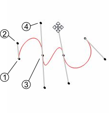
Draw Bezier
The draw Bezier tool allows building Bezier curves. For each section of Bezier you’ll have to click four time (see below).
Defines your starting point
Defines the direction of your Bezier at the starting point
Defines your arriving point
Defines the direction of your Bezier at your arriving point
Modify Bezier
While drawing your Bezier curves, you can modify them using the option Modify Bezier. This option allows you to move your starting/arriving points also the orientation and intensity of the way.
Warning
Your Bezier curve can only be edited while drawing. Once you validate it, it becomes regular segments of line and can therefor only be edited as such.
Bezier Settings
In the Bezier settings you can manage the parameters of the Bezier. You have access to two styles of parameters:
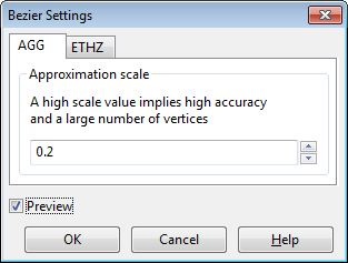
The AGG fashion: Have only one parameter, the higher your value the more complex your curve (more vertices).
The ETHZ fashion: With the ETHZ method you can play on two parameters; the maximum number of points for each segment and the width tolerance. While the maximum number is easy to understand the width range defines whether a vertex is created or not, the higher the range, the more simple your curve.
The Preview option displays how the line will be created regarding the parameters. It is only available while drawing a Bezier.
Note
The Bezier settings are specific to the project, the configuration remains even if you close and re-open the project
Remove last vertex
While drawing a line or a Bezier, this tool allows you to remove your last vertices. This tool works only during the vectorization process. This tool will not remove vertices from a validated line.
Edit Vertex
Allows modifying the geographical coordinates of the vertices.
Select a feature
activate the tool ; The following window pops up
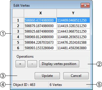
Geographical coordinates of the vertices defining the geometry of the feature
The coordinates can be directly edited in the table.
[+]: add a new Vertex, the insertion is made after the current selection. The X,Y coordinates have to be edited. The insertion of a vertex without coordinates provokes an error message at the update of the geometry.
[-]: suppression of the selected vertex.
[Display Vertex]: Visualization of the selected vertex.
Update or cancel the current modifications
Selected feature ID
Number of vertices of the selected feature
Insert vertex
This tool allows you to insert vertices on a selected line. To do so activate the tool with the option insert vertex in the edition menu or with the I shortcut and simply click on your selected line where you want an additional vertex.
Delete vertex
The Delete vertex tool allows you to delete any vertices on a selected line. To do so simply activate the tool selecting the option delete vertex in the Edition menu or with the C shortcut and aim for an unwanted vertex, it will be obliterated.
Delete selected feature
allows deleting the selected features
Select the feature(s)
Use the option of the menu or use the Delete or Backspace key
In the case of a multiple selection, a window appears asking a confirmation of the suppression.
Cut line
The cut lines option allows cutting lines. The cut can only be done on a vertex.
Select a line
Activate the tool with the menu or with the shortcut (Ctrl+X) ; the tool cursor displays
click on the vertex where the division must be done
The two lines will then have the attributes of the original line.
Merge Line
Allows merging the selected lines. The selected lines have to be adjacent, the lines must have a begin/end vertex in common.
Select lines
Activate the tool : several cases are possible:
Same attributes =>no consequences
Different attributes => the user has to define the attributes to keep
1 non attributed object => the user has to define the attributes to keep
Same polarity => no consequences
Different polarities => the polarity becomes left to right
Create intersection
Allows creating intersections between lines which cross themselves. All the segments created will keep their previous attributes
Select a line which cross another one.
Activate the tool with the menu or with the Ctrl+I shortcut.
Important
The tool will generate very small lines if they cross themselves on a vertex
Flip line
The Flip line option allows to reverse the polarity of the selected line. To check the polarity of the line you have to either open the vertex editor (see Edit Vertex) and check the coordinates of the first vertex or use the oriented line symbology (see Lines) . The tool can be used on multiple lines at once.
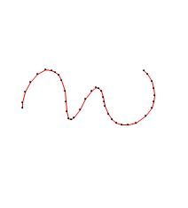
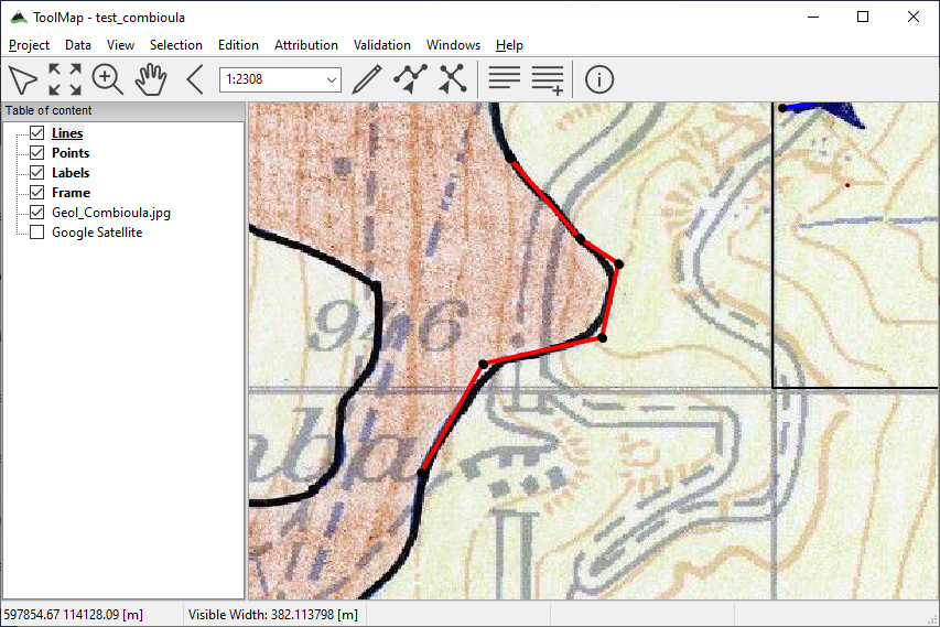
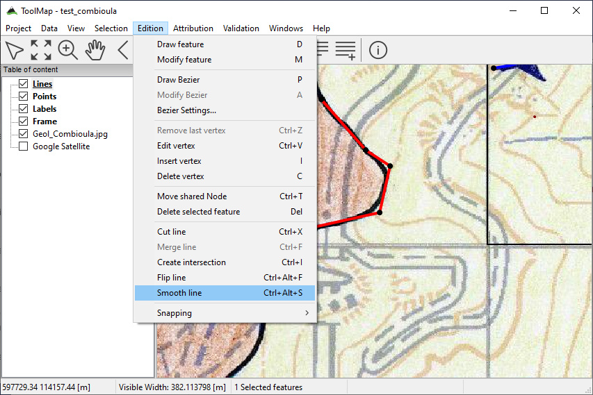
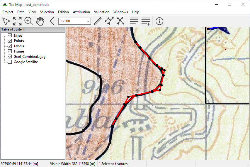
Smooth line
The Smooth line option allows adding nodes using the Chaikin algorithm. A line must be selected in edition mode before applying the smoothing. Every application of the algorithm corresponds to an iteration of the smoothing. When finished, press Enter to keep the changes.
Select a line in edition mode
Apply the smoothing
Result of a single application of the smoothing
Result of a second application of the smoothing
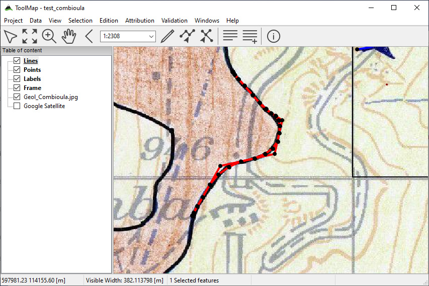
Final result after pressing Enter

snapping
The snapping tools are accessible via the menu
During the vectorization of a point or line feature, the snapping function allows to hang on the nodes of an existing feature. The snapping can be done on the features of the active layer (i.e. current edition) and/or on features belonging to other layers (construction layers and vectorial support themes)
Snapping panel
The snapping panel (Ctrl+G) is defined by the following elements:
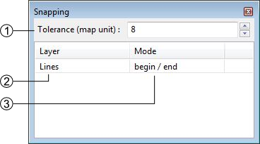
The capture tolerance of nodes
The involved layers
The mode of snapping used for the involved layerlayer. You can choose between :
None: the snapping is disabled on this layer.
Begin/end: the snapping occure only on the first and last vertices of a line.
All vertex: the snapping occure wherever there is a vertex.
Snapping display
Using the option Show snapping radius on map (Ctrl+Alt+G); you will display a circle in the top left corner of the visualization window representing the snapping tolerence.
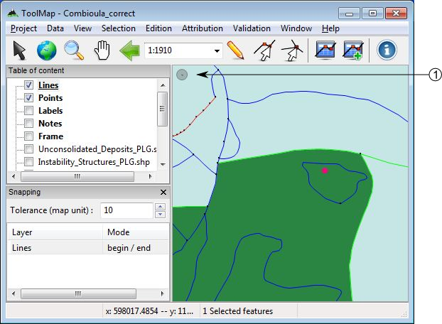
Snapping tolerance
The options Add layer… and Remove layer… are both accessible in the menu or with the contextual menu of the snapping panel.
Note
The Space or Shift keys temporarily deactivate the snapping. You can use it while working in the vicinity of existing nodes to prevent undesirable snapping.