Spatial Data management
The data management is made through the Data menu, it contains the following elements:
- Link data... (
Ctrl+O): reference a support layer which will be displayed in your project- Unlink data... (
Ctrl+W): unlink a layer- Add Web data... (
Ctrl+Alt+W): Add web data such as Google / Bing images- Import data: import data into one of your construction theme
Link data
The option allows loading some support themes for the vectorization of the construction layers. Those support themes can be vector data (*.shp) or raster data (*.tif, *.JPG and Esri’s binary GRID).
In the opposite of the construction layers, the support themes are not stocked in the project but only referenced.
Rotation
Some of your files may have rotation information, which is not yet supported by ToolMap. In that case you will see the following message:
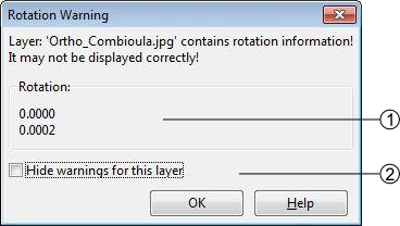
- rotation information
- display option
This message will pop up every time you make an action regarding the layer (including trivial actions like zoom or pan), so be sure to convert your images into non-rotated rasters (see Rotation Warning). If the rotation is insignificant, you may prefer to simply ignore the message by checking the option Hide warnings for this layer. This option prevent the appearance of the message for the current session, but it will pop again the next time you launch your project.
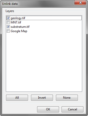
Unlink data
The option allows removing specified support layers from the project. Those layers aren’t deleted but simply removed from the project.
Add Web Data
The option allows adding web data as support layers. The list of supported web data are listed in the picture bellow.
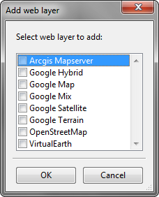
Note
Web data layers will not be displayed if there is no data into the actual project. Web layers aren’t able to know which part of the world should be displayed if at least one local support layer or one construction layer isn’t displayed.
Warning
Currently, web data layers didn’t work behind a proxy. This will be improved in futures versions
Import data
The option allows to import some existing information into the construction layers. You can only import lines or points geometries. The process is made in several successive steps. The import might finish earlier if the next steps are not relevant (e.g. there is no attribute).
Step 1
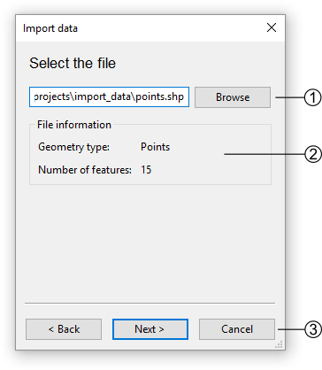
ToolMap supports the import of csv (points only) or shapefiles (points, lines, frame, or labels)
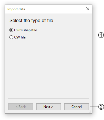
- The file type option allows two types of data, choose the one you want to import
- Go to the next step or cancel the operation
Step 2
If you choose to add a shapefile the following step comes ahead
If you choose to add a CSV file, the following step comes ahead
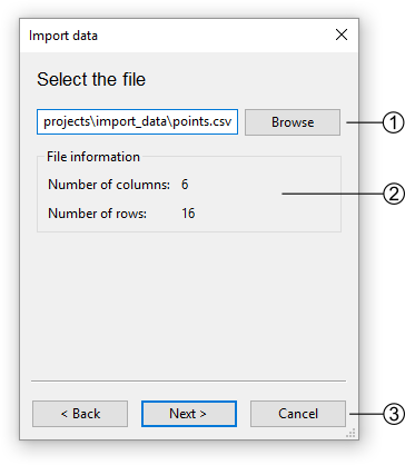
- Path to the CSV file
- Information about the CSV file
- Go back to Step 1 or continue to Step 3 - for CSV files only
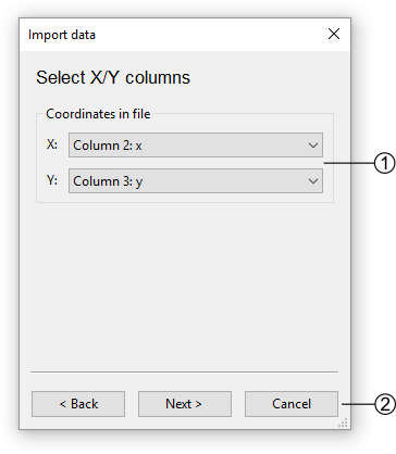
Step 3 - for CSV files only
The CSV files are composed of columns of data separated with commas. The columns containing the X and Y coordinates must then be selected.
Step 4
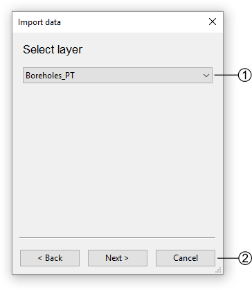
Select the target to import the data.
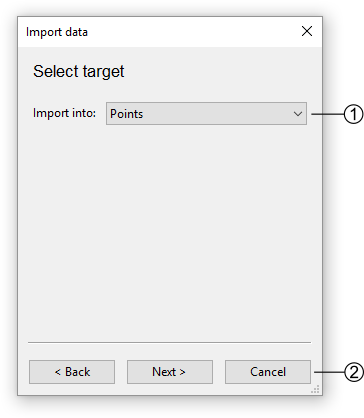
- List of possible targets to import the data
- Go back to Step 3 - for CSV files only or continue to Step 5
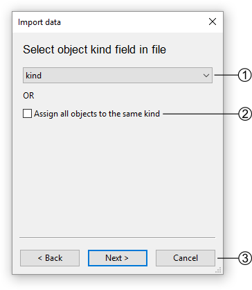
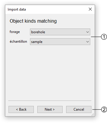
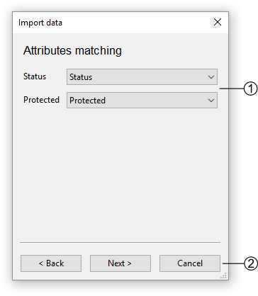
Step 9
Define the matching of the enumerations with the database (if applicable).
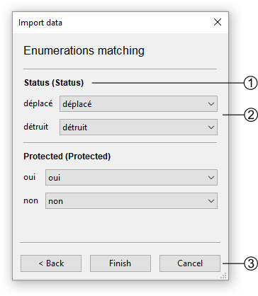
- All attributes that are of enumeration type are listed. The first attribute name is the one from the database and the second is the one from the file.
- All the field values from the file for that attribute are listed. On the right-hand side, a list of all enumeration values for that attribute from the database is displayed. The correspondence must be established.
- Go back to Step 8 or to terminate the import.
Table of contents options
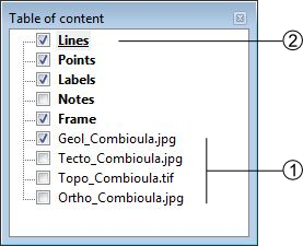
 Activate the display of the layer
  Deactivate the display of the layer
- Edition mode activated: the layer is underlined
contextual menu
The contextual menus are opened by right-clicking on a layer of the table of contents. They vary according to the selected layer.
Construction
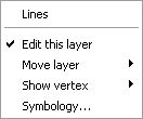
Support
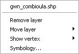
- Name of the layer
- Edit this layer (construction layers only)
- Remove layer (support themes only)
- Move the selected layer in the table of contents
- Display management of the vertex (line and polygon layers type only)
- Symbology management. This option can also be activated by double-clicking on the layer. (see Symbology)