Spatial Data management
The data management is made through the Data menu, it contains the following elements:
Link data… (Ctrl+O): reference a support layer which will be displayed in your project
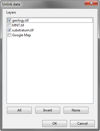
Unlink data… (Ctrl+W): unlink a layer
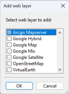
Add Web data… (Ctrl+Alt+W): Add web data such as Google / Bing images
Import data: import data into one of your construction theme
Link data
The option allows loading some support themes for the vectorization of the construction layers. Those support themes can be vector data (*.shp) or raster data (*.tif, *.JPG and Esri’s binary GRID).
In the opposite of the construction layers, the support themes are not stocked in the project but only referenced.
Rotation
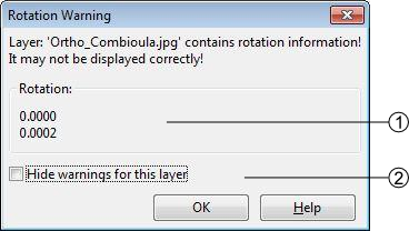
Some of your files may have rotation information, which is not yet supported by ToolMap. In that case you will see the following message:
rotation information
display option
This message will pop up every time you make an action regarding the layer (including trivial actions like zoom or pan), so be sure to convert your images into non-rotated rasters (see Rotation Warning). If the rotation is insignificant, you may prefer to simply ignore the message by checking the option Hide warnings for this layer. This option prevent the appearance of the message for the current session, but it will pop again the next time you launch your project.
Unlink data
The option allows removing specified support layers from the project. Those layers aren’t deleted but simply removed from the project.
Add Web Data
The option allows adding web data as support layers. The list of supported web data are listed in the picture bellow.
Note
Web data layers will not be displayed if there is no data into the actual project. Web layers aren’t able to know which part of the world should be displayed if at least one local support layer or one construction layer isn’t displayed.
Load WMS data
The opens the WMS Browser window, which is used to connect to a Web Map Service (WMS), browse available layers, and select specific layers to export (and add to the project). The selected layers will be exported to xml files and can be added to any ToolMap project as support layers (similar to other support layers). It is however recommended to use WMS layers with the same projection as the project to benefit from the best rendering quality.
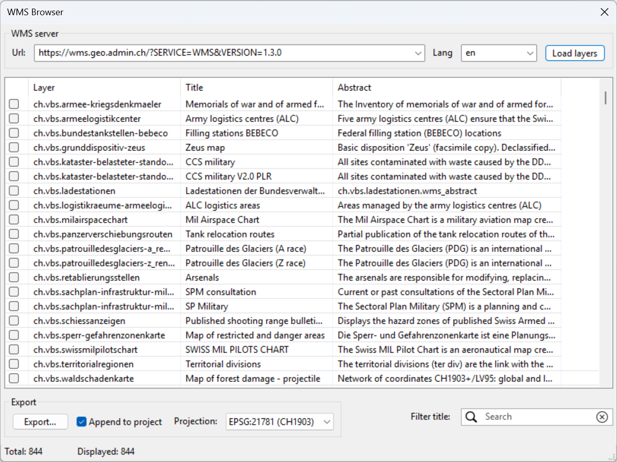
The top part of the window contains controls for connecting to a WMS server:
WMS Server URL: at the top of the window, the URL field lets you specify the address of the WMS server. This is typically a query URL following the WMS standard, such as:
https://wms.geo.admin.ch/?SERVICE=WMS&VERSION=1.3.0. You can either type the URL manually or select a pre-recorded one from the drop-down list. Once the URL is set, pressing the Load layers button to the right will query the server and populate the list of available layers.Language Selector: next to the URL field, there is a language selection drop-down. It allows you to choose the preferred language in which metadata such as layer titles and abstracts are displayed.
Load layers button: after entering the WMS server URL and selecting the language, clicking this button will initiate a request to the server to retrieve the list of available layers. The layers will then be displayed in the table below.
Layer Table: once the layers are loaded, they appear in a scrollable table in the center of the window. Each row corresponds to a WMS layer provided by the server. The table contains the following columns:
A checkbox for selecting the layer.
Layer: the internal layer identifier.
Title: a human-readable title of the layer.
Abstract: a brief abstract describing the content or purpose of the layer.
Users can scroll through the list or use the filter tool at the bottom to narrow down the displayed layers. Multiple layers can be selected at once using the checkboxes.
Search and Filter: below the table, there is a search box labeled Filter title, which allows you to dynamically filter the list of layers by title.
Projection Selector: to the right of the filter, you can select the desired map projection from a drop-down menu. The list contains the projections supported by the WMS server. By default, the projection is set to the project projection if supported by the WMS server. Changing the projection will affect the exported layers’ coordinate reference system.
Append to Project: beneath the table is a checkbox labeled Append to project. When enabled, this ensures that selected layers will be directly added to the currently open ToolMap project upon export.
Export Button: finally, the Export… button initiates the process of exporting the selected layers and adding them to the project.
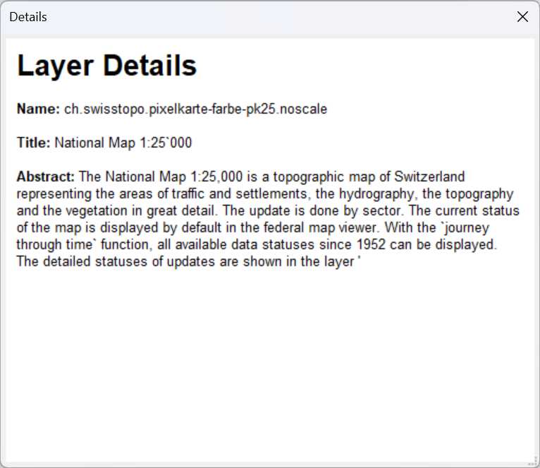
When double-clicking on a layer in the table, the WMS Layer Details window opens. This window provides detailed information about the selected WMS layer, including its title, name, and full abstract.
Import data
The option allows to import some existing information into the construction layers. You can only import lines or points geometries. The process is made in several successive steps. The import might finish earlier if the next steps are not relevant (e.g. there is no attribute).
Step 1
ToolMap supports the import of csv (points only) or shapefiles (points, lines, frame, or labels)
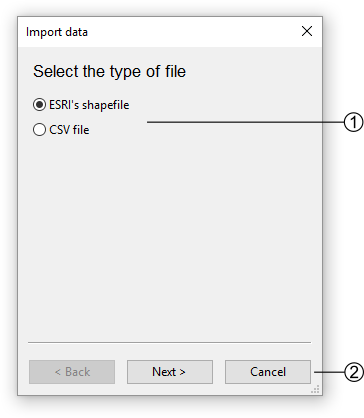
The file type option allows two types of data, choose the one you want to import
Go to the next step or cancel the operation
Step 2
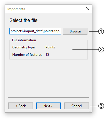
If you choose to add a shapefile the following step comes ahead
If you choose to add a CSV file, the following step comes ahead
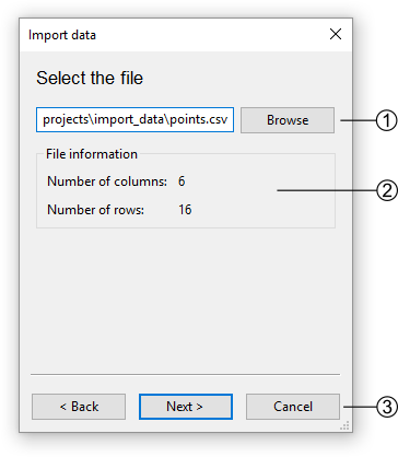
Path to the CSV file
Information about the CSV file
Go back to Step 1 or continue to Step 3 - for CSV files only
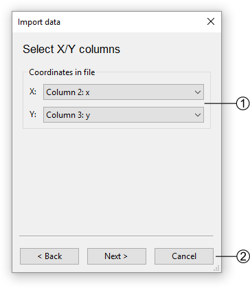
Step 3 - for CSV files only
The CSV files are composed of columns of data separated with commas. The columns containing the X and Y coordinates must then be selected.
Step 4
Select the target to import the data.
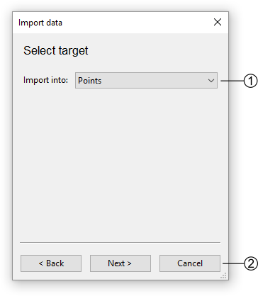
List of possible targets to import the data
Go back to Step 3 - for CSV files only or continue to Step 5
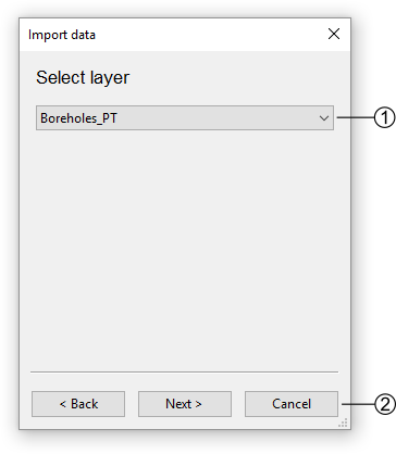
Step 5
Select the layer to import the data (if not a frame).
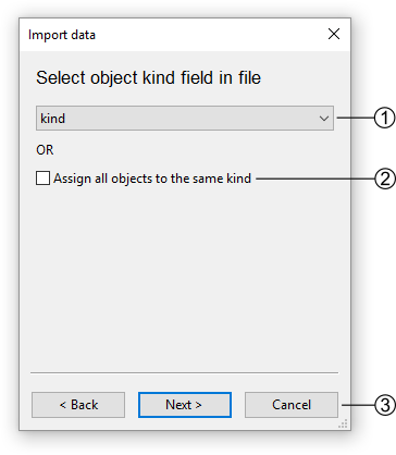
Step 6
Select the object kind field.
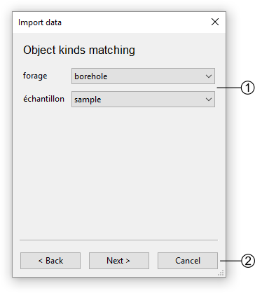
Step 7
Define the matching of the object kinds with the database.
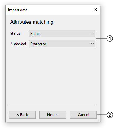
Step 8
Define the matching of the attributes with the database (if applicable).
Step 9
Define the matching of the enumerations with the database (if applicable).
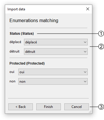
All attributes that are of enumeration type are listed. The first attribute name is the one from the database and the second is the one from the file.
All the field values from the file for that attribute are listed. On the right-hand side, a list of all enumeration values for that attribute from the database is displayed. The correspondence must be established.
Go back to Step 8 or to terminate the import.
Table of contents options
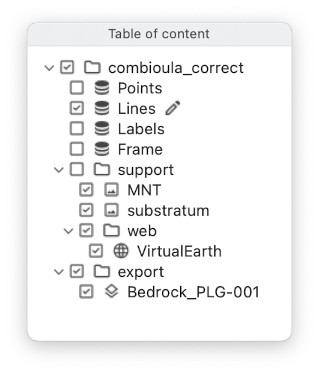
 Activate the display of the layer / group
 Deactivate the display of the layer / group
Note
A layer will only be displayed if all its parents are also displayed
 Edition mode activated, only allowed for construction layers
  .
.
Contextual menu
The contextual menus are opened by right-clicking on a layer of the table of contents. They vary according to the selected layer.
Construction layers

Menu for lines or frame layers
Menu for points and labels
The menu entries correspond to the following actions:
Edit Layer Put the selected layer in edition.
Show Vertex Allows you to select which vertex should be displayed.
Symbology… Display the symbology dialog (see Symbology).
Important
For editing to work properly, the theme must be in edit mode and selected!
Support layers

Menu for shapefile support layers.
Menu for raster / web raster support layers.
The menu entries correspond to the following actions:
Remove layer Remove the selected layer from the project.
Show Vertex Select which vertex should be displayed.
Labels… Place text next to the geometric object. It is mainly used for points.
Save Symbology… Save the current symbology into an external file (.tly).
Load Symbology… Load the symbology from an external file (.tly).
Symbology… Display the symbology dialog (see Symbology).
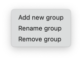
Groups
The menu entries correspond to the following actions:
Add new group Create a new group. If a group is selected, the new group will be added as its child.
Rename group Change the group name.
Remvove group Remove a group from the project.
Warning
A group can only be deleted if it is empty.